The Z+ has two programmable output pins that can be controlled from the front panel or via a computer through the bundled graphical user interface over USB. These can be used to control isolation or polarity reversal relays, for example, without the need of a separate programmable logic controller (PLC). The programmable outputs are located on the rear of the units, with slightly different layouts for the low voltage (10V – 100V) and high voltage (160V – 650V) models.

Pinouts for low voltage (left) and high voltage (right) models

On the low voltage and high voltage models the programmable outputs are located at pins 1 and 6, with slightly different connectors on each model. Pin out diagrams are shown above. Internally the programmable outputs are controlled via open collector FETs each shunted by a 27V Zener diode. The outputs are rated to 25V maximum and can sink a maximum current of 100mA. These values should not be exceeded.

The internal characteristics of the programmable outputs
Combining programmable pins with relays
The programmable pins can be used in conjunction with relays to give additional functionality to the Z+ power supplies. Two useful examples are shown below
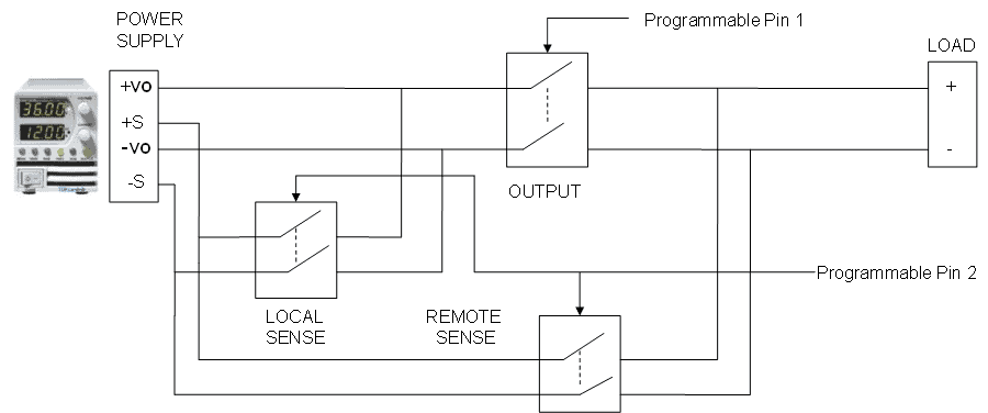
Example showing the use of the programmable outputs and relays to switch between local and remote sensing.

Example showing the use of the programmable outputs and relays to switch polarity at the load